Refractory Insight – Part 2: Testing
Welcome to my second insight article for Remet UK. If you didn’t catch my first insight, on “Slurry Testing, Common pitfalls and Mistakes.”, you can find it here: Slurry Testing, Common Pitfalls and Mistakes.
As we have seen in previous Insight articles written by Bob Brown, Gavin Dooley and myself, physical properties of all materials used in the investment casting process are important. Being able to measure these properties will help you to control your process
Within our laboratory we can measure many of the properties required to be sure of consistent products. The following insight will highlight some of the test methods we utilise to test refractories in our Rochester laboratory.
Sampling.
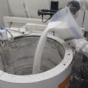
When testing ceramics, a representative sample is needed, so we know what we are testing is what we have. However, during transport, refractory can separate and settle with in the bag. Therefore, the first thing that is required is to sample the refractory correctly. At the Remet lab riffling a whole bag using a sample splitter is the desired method.
A whole bag of refractory is poured into a sample splitter, which separates the sample into two halves using alternating chutes. These two sub-samples are deposited below the sample splitter in two vessels. One half can then be discarded, whilst the retained half is run through the sample splitter again. This process is repeated until you have a sample size suitable for your testing requirements. See image 1.
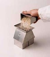
Image 1, Sample Splitter

Image 2, A Stylised Sample Splitter
Sieve testing.
Sieve analysis is a quick, cheap and easy test to carry out to determine the particle size distribution of your refractory. Sieves that are suitable for the grade of refractory used are weighed empty, and stacked with the largest diameter sieve at the top, the smallest at the bottom, and a pan under this to catch all the fines. This stack is then placed on to a sieve shaker.
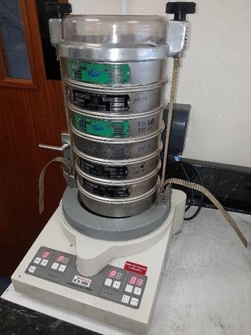
Image 3, A Sieve Shaker, and Sieves
A representative sample of refractory between 100g and 200g (record the weight used) is poured into the top sieve, and stack of sieves will have it lid placed on, and then will be secured. The sieve shaker can then be started, the smaller the particle the further down the sieves stack they will fall until they are caught by a sieve they cannot pass through, larger particles will be caught further up. This work can be carried out dry, or wet. Wet sieving is usually carried out for finer materials, such as flours, which may agglomerate.
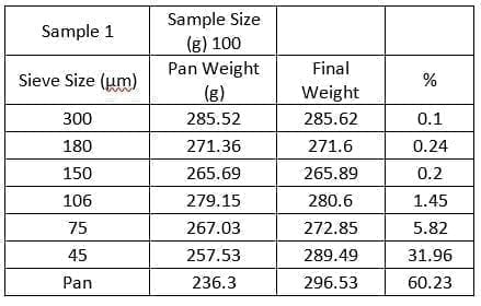
Below, I have included a conversion table for different sieve standards, this is very useful when comparing materials from different regions.
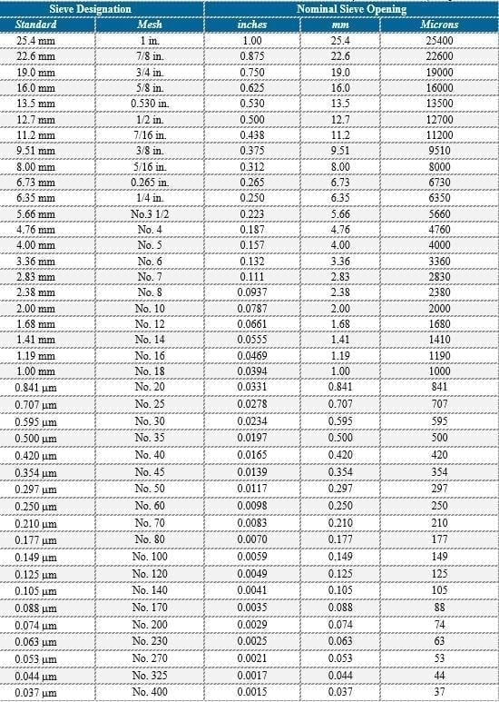
It is worth noting that a + symbol before the sieve mesh indicates the particles are retained in that sieve. A – symbol indicates that the particles pass through the sieve. Usually 90% or more of the particles measured will lie within the indicated range.
Particle Size Analysis.
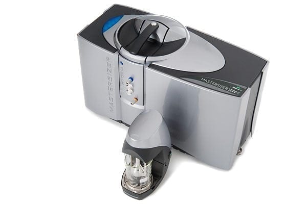
Image 4, A Malvern Mastersizer
Particle size analysis (PSA) measures the particle size range of a sample, that has been dispersed into a liquid before testing. PSA utilises laser light being scattered to calculate the sizes of particles present. This test method can be very quick to perform, and the results very reproducible
In PSA “Laser diffraction measures particle size distributions by measuring the angular variation in intensity of light scattered as a laser beam passes through a dispersed particulate sample. Large particles scatter light at small angles relative to the laser beam and small particles scatter light at large angles” (Malvern. 2017)
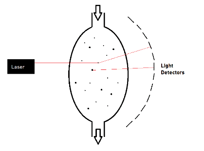
Image 5, An Overview of How PSA Works
This test method is particularly useful for finer materials, that would normally need wet sieve analysis, this helps to retain all the fines in the sample, and eliminates the difficulty of getting the material through the sieves. However, the test is also still god for larger particle sizes. Below is Chart 1, which shows a representative distribution for a refractory sample. Refractories are often normally distributed, the presence of a secondary peak, or more peaks, is a good indication of a blend of refractories.
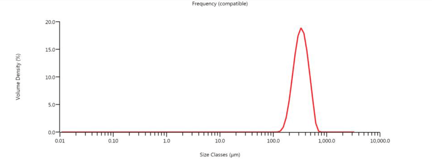
Chart 1, PSA Results
Dilatometry.
The last test I wish to talk about in this insight is Dilatometry. This test can be used to look at the expansion and contraction of ceramics, and help to identify the temperature needed to sinter the refractory found within the slurry/shell. The thermal expansion characteristics are material specific, and will have a large influence on the dimensional structure of your shell. (M. Weissenbacher and T. V. Krumrei, 2017.) Below is an image of the Orton Dilatometer found in the Rochester lab.
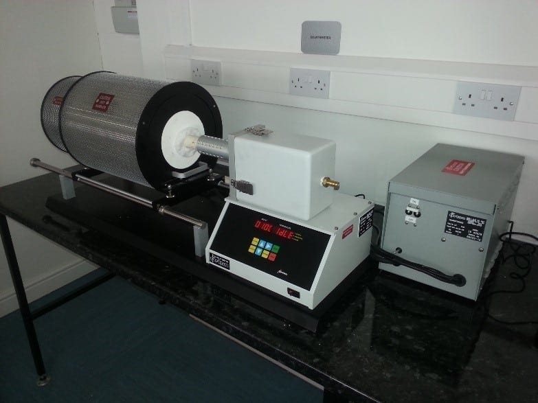
Image 6, Orton Dilatometer
Samples are prepared by pouring a small amount of slurry into a mould to create pellets. These are then measured, and placed into the dilatometer.
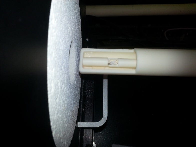
Image 7, A Pellet of Shell in the Dilatometer.
The shell is then fired, up to a desired temperature. The dilatometer will then measure the expansion, or contraction of the material as it heats up. The graph below shows a standard material tested up to 1600 °C using a dilatometer. You can see the material expanding as it is heated initially. However, past 1300 °C, the material rapidly contracts. This is densification, or sintering of the material, this process will provide a lot of strength in the shell when pouring parts.
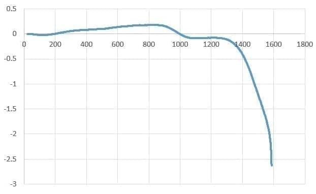
Chart 2, A Dilatometer Result for a Standard Material
Refractories Within the Investment Casting Process.
So why is building a picture of the refractory you are using important?
Refractories make up 80 – 85% of the standard slurry blend. This isn’t a hard-set rule however.
Refractories are prone to drop out of suspension ion the slurry tank is mixing is not adequate.
It is essential to keep the particle size distribution consistent with in you process to help reduce defects.
Rainfall sanding of Stucco coats, if not properly controlled, can cause the stucco to penetrate too deep in the layer of the shell, potentially creating defects.
More on this will be covered in a later Remet Insight.
References
EngNet. 2017. Grain Fineness Number. [ONLINE] Available at http://www.engnetglobal.com/tips/glossary.aspx?word=Grain+Fineness+Number [Accessed 16 May 2017].
M. Weissenbacher and T. V. Krumrei, 2017. Refractory raw materials selection and inspection: test methods and impact on shell performance, Presented at Inspection Capabilities for Tomorrow’s Foundry, EICF EURO Workshop, Brunoi Czech Republic, 10 – 12 May 2017. Pages 353 – 376.
Malvern. 2017. Laser diffraction particle sizing technique. [ONLINE] Available at: http://www.malvern.com/en/products/technology/laser-diffraction/. [Accessed 03 April 2017].
Sigma Aldrich. 2017. Particle Size Conversion Table. [ONLINE] Available at: http://www.sigmaaldrich.com/chemistry/stockroom-reagents/learning-center/technical-library/particle-size-conversion.html [Accessed on 08 May 2017].
Disclaimer
Contact your nearest REMET Sales Office regarding product specifications.
Contact your REMET Territory Manager and visit www.remet.com if you have any questions or require additional information.
Information and/or recommendations based on research and technical data believed to be reliable. Offered free of charge for use by persons with technical skills, at their own discretion and risk, without guarantee of accuracy REMET makes no warranties, express or implied, and assumes no liability as to the use of its products or of any information pertaining thereto. Nothing herein is intended as a recommendation to infringe any patent.
< Back to insights