Factors affecting shell strength and slurry life – a dive into the chemistry and microstructural effect
Welcome to my first insight article on ceramic shell moulds. I am aware that there are already thousands of papers and experimental work being published throughout the years on this field and I believe it is important to review their work every now and then to keep up with the pace of foundry production.
This paper is to give an overview on the factors that will help to produce better ceramic shell system for investment casting.
Introduction
Ceramic shell moulds in investment casting is essentially compromised of ceramic stuccos, ceramic filler and binder usually made from ceramic colloidal sol. Ceramic stuccos and filler is selected based on mould drying effectiveness, made-up slurry characteristics, mechanical strength, refractoriness. Colloidal sol however is the ‘glue’ that hold the discrete particles in the sol and react with the refractory particles during the drying process and subsequently the autoclaving and firing.
Stable concentrated silica sols with negatively charges surface only became available in the 1940s after it was learned how to make uniform colloidal particles larger than about 5 nm in diameter and finding the optimum amount of base to stabilize (Iler, 1979). Until in 1961, Alexander and Bolt developed a concentrated positively charged surface silica sol. This is usually a low pH (3-5 pH) sol binder.
The use of colloidal silica aquasol with negative charged silica sol stabilized with sodium are still the most commonly used binder system. In recent years however, there are rising use of modified silica sol binder system. This is due to better stability characteristics of the binder.
The green strength of shell was found mainly dependant on the binder silica sol characteristics and polymer (Rusher, 1974). In general, the strength of unfired shell is a function of the
- Concentration of binder silica in the slurry
- Particle size of the silica
- Alkali content of the binder silica sol
- Concentration of polymers
- Characteristics of polymers
- Drying condition
The fired strength of shell was found to be highly dependent on the refractoriness of the bonded particles and the binder solids (Figure 1). In general, the strength of fired shell is a function of
- Firing temperature and time
- Refractoriness of the bonded particles
- Sodium content of the binder sol
- Impurities in ceramic filler
If a colloidal silica system is used, the silica will transform to cristobalite during the firing process and this will be discussed later.

Figure 1: Interaction of refractories and silica binder (GRACE). Hydroxyl group on sol particles surfaces condense and form siloxane bonds between the particles.
The shell strength is significant as it faces different stresses in various stages of the Investment casting process (Jones & Yuan, 2003)
- Mechanical stresses during the dipping (due to buoyancy of slurry) and rate of drying
- Contraction and expansion forces of wax pattern as the latent heat is extracted during the drying process even though the room temperature remain constant
- Thermal expansion of wax during dewaxing process inducing stress on shell
- Hot creep due to pressure from molten metal during pouring and mould clamping on roll overs
- Thermal shock when putting in and removing from the firing oven
- Thermal shock during metal pouring
- Sufficiently weak to prevent hot-tearing in susceptible alloys
Effect of Shell preparation and Testing variables on shell characteristics
There are many other factors other than the standard slurry preparation that could affect the shell strength. This could be the practice of pre-wetting in silica sol, the immersion time of pattern in slurry, dripping time, stuccoing technique (fluidised bed or rainfall sander), firing temperature and firing time.
Rusher found pre-wetting before slurry dipping produces thinner shells therefore reduces shell strength. He did not explain the reason behind this but the idea of pre-wetting is to allow a monolayer of silica sol adsorbed on the less hydrophilic surface either the wax pattern or the ceramic surfaces prior to slurry dipping. Regarding the wax pattern surface, hydrophilic surface treatment had been introduced during the pattern wash stage. In the perspective of consequent ceramic coatings surface, longer immersion of moulds in slurry which also contains silica sol is sufficient to wet the ceramic surfaces. Prewetting is used to access smaller geometries in complex parts and allows for one slurry to coat multiple geometries without the need to change the viscosity regularly. Prewetting reduces the interstitial viscosity between the part and the slurry, allowing for a more fluid slurry to coat the slurry (Dooley & Kavanagh, 2012). In other words, prewetting can be used to control slurry viscosity. Dooley and Kavanagh found that prewetting produces a shell with no defined laminar structure (see Figure 2&Figure 3). This homogenous structure causes the shell to be weaker in relative to a laminated structure (Figure 4) (Dooley & Kavanagh, 2012). As far as the author understand, pre-wetting is a redundant step of the process in terms of shell strength. Introducing additional silica sol from pre-wetting into the slurry during the slurry dipping also will changes the characteristics of the slurry.

Figure 2: Shell system with pre-wet before coats 1,2,3
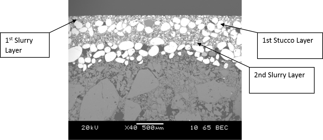
Figure 3: Shell system with no Prewet (Dooley & Kavanagh, 2012)
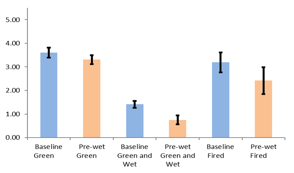
Figure 4: Effect of Prewetting on shell mechanical strength
Dripping time after slurry dipping is another important aspect to address. If the mould is hand coated which commonly done for test bar preparation, will cause the shell properties to vary from personnel to personnel. This is because even if the immersion and dripping time is set constant, the total amount of slurry remains on the surface do varies. A simple way to benchmark and record this difference is by weighing the mould after each coat and compensate in the following coating if necessary.
The major role of stucco is to build shell thickness quickly. The more stucco that is applied and the larger the diameter of the stucco particles, the thicker will be the dried shell and the higher load bearing is the shell. However, modulus of rupture decreases as the amount of stucco on the shell increases as the shell thickness term in the equation is more influential. Generally, stuccoing with rainfall sander shows higher shell strength than fluidised bed (Jones, Yuan, & Blackburn, 2007). This is due to the compactness of shell contributed by the potential energy of stuccos in the rainfall sander methods.
Firing temperature and time is another important factor. Too long of a firing at high enough temperature, the silica will start to devitrify from amorphous silica to a crystalline form and moulds starts to creep and soften if impurities present in the mould. The conversion to crystalline form silica can occur at as low as 870 °C depending on the sodium content in sol and other impurities. In the cooling process after metal pouring, the conversion of ß-phase cristobalite to alpha-phase at between 275 to 200 °C introducing differential volume contraction between the two phases. This produces microcracks within the shell system and is required to ease the shell removal process. But the effect of temperature is more prominent than firing time. This factor is important especially on moulds that requires pre-firing. Pre-firing is carried out either before storing the moulds for later use or to clean the moulds free from loose ceramic particles prior to firing for metal pouring.
Other characteristics of shell such as mould permeability is important. It helps to let air escaped through the porous shell and reduces entrapped air in castings. Polymers or other organic materials can play an important role to improve the permeability of fired shell. Another important parameter to consider is the thermal conductivity of the shell. Ceramic shell has very high heat capacity, this additional energy if not well dissipated during the cooling process, it will cause the casting to have shrinkage porosity or even hot tearing. The area where higher heat energy accumulated is commonly known as hot spots.
Effect of binder and flour characteristics on shell characteristics
Refractoriness
Refractoriness or chemical stability is important to avoid reaction with metal and affect the surface finish (Jones & Yuan, 2003). Depending on the casting alloys, some such as titanium aluminide, stainless steel or Inconel alloys requires higher inertness of shell especially on the prime coat. The refractoriness of most common material used in investment casting can be arrange as follow starting from least inert material: Fused silica < Alumino-silicates < Zircon < Alumina < Zirconia < Yttria. Ellingham diagram is a good reference to decide what is the ideal refractory to be used. The diagram provides the information of the affinity of materials forming oxides.
Colloidal particle size
The rate of gelling appears to be proportional to the total area of silica surface present in a given volume of sol (Iler, 1979) by assuming that the ionic concentration and pH is constant. In other words, sols having the same ratio of concentration to particle diameter gel at about the same rate. For instance, 5% concentration of 5 nm particle size sol will gel at the same time as a 22% concentration of 22 nm particle size sol.
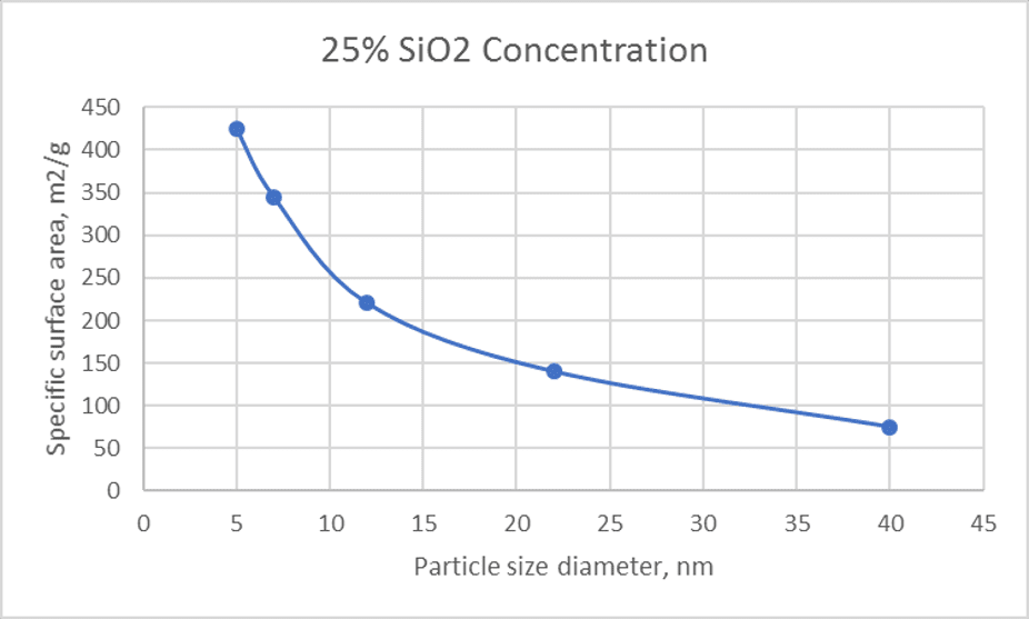
Figure 5: Relationship between particle size and surface area
The mechanical strength is also directly related to the particles size of silica. Many people aim for specific silica concentration when considering a new product, but what is important to consider is the specific surface area and not solely the silica concentration (see Figure 5). The smaller the particle size of the binder particles, the greater will be the maximum unfired strength (Rusher, 1974). He also found that the unfired MOR is a function of alkali content of the binder sol and not silica particle size as is commonly thought. The unfired MOR increases as the alkali content increases up to about 2 wt % and then remain constant. In terms of fired MOR test samples however, the increment of alkali (sodium specifically) to a certain concentration (1 wt%) increases the sintering thus strength. Further increasing the sodium content (> 3wt%) will then increases the devitrification of silica thus weaker shell when tested after shell cooling. Of course, the smaller silica particles will also help to improve the fired strength.
It is a very similar case for fired strength. The larger the surface area, the more the sintering sites during the firing process. Larger particles are better close pack prior to immobilization on dry-down and will result in higher fired strength.
Rusher found a relationship to predict the optimum amount and particle size of silica binder in relation to the refractory particles to obtain a highest possible unfired and fired modulus at rupture.

Filler particle size
The slurry viscosity saturates at a solid loading, ie. 85-88 % depending on the particles size and particle size distribution. Generally, the smaller the particle size of flour, the higher the viscosity. The narrower the particle size distribution, the higher the viscosity at the same solids loading.
Conclusion
It is important to re-evaluate the materials and shelling technique to optimise the process of investment casting. Production rate and quality of casting is always expected to be ever improving and therefore a sound mould is important to deliver this expectation. Regular testing is required to assure the raw materials and the shell has the optimum characteristics for the process to reduce mould failure.
Thanks for reading.
References
Dooley, G., & Kavanagh, A. (2012). Development of Foundry Casting Methods for Cost-Effective Manufacture of Medical Implants. 58th Technical ICI Conference. Convington, KY.
Iler, R. K. (1979). The Chemistry of Silica. John Wiley & Sons, Inc.
Jones, S., & Yuan, C. (2003). Advances in shell moulding for investment casting. Journal of Materials Processing Technology, 135(2-3) p. 258-265.
Lee, K., Blackburn, S., & Welch, S. T. (2017). A more representative mechanical testing of green state investment casting shell. Ceramics International, Volume 43, 268-274.
Rusher, R. L. (1974). Strength Factors of Ceramic Shell Molds – Part 1. Cast Metals Research Journal, 149-153.
< Back to insights