Investment Casting Permeability
Introduction
My first three articles (Strength Part 1 | Part 2 | Part 3) dealt with the strength of materials, particularly wax and shell systems and what this means for your shell system. As discussed it is a complex loading regime and failure scenario when a shell fails. In future I may return to this to discuss how a shell fails however another intrinsic property of a shell system is the permeability.
The permeability is a key property of any shell and can be responsible for the success/ or failure of a shell system. The permeability is a key property of any shell and can be responsible for many casting related defects like cold shut and non-fill. It can also allow for wax to expand into the shell during de-wax, reducing shell cracking. Firstly, we must discuss what is meant by the term permeability, how it is measured and how it can affect properties of a shell.
Permeability vs. Porosity
The first thing to understand is permeability is not how many voids are within a shell. There is a close yet different relationship between permeability and porosity:
- Porosity is a measure of how many voids are present within a shell system
- Permeability is a measure of easily a fluid can move through the shell
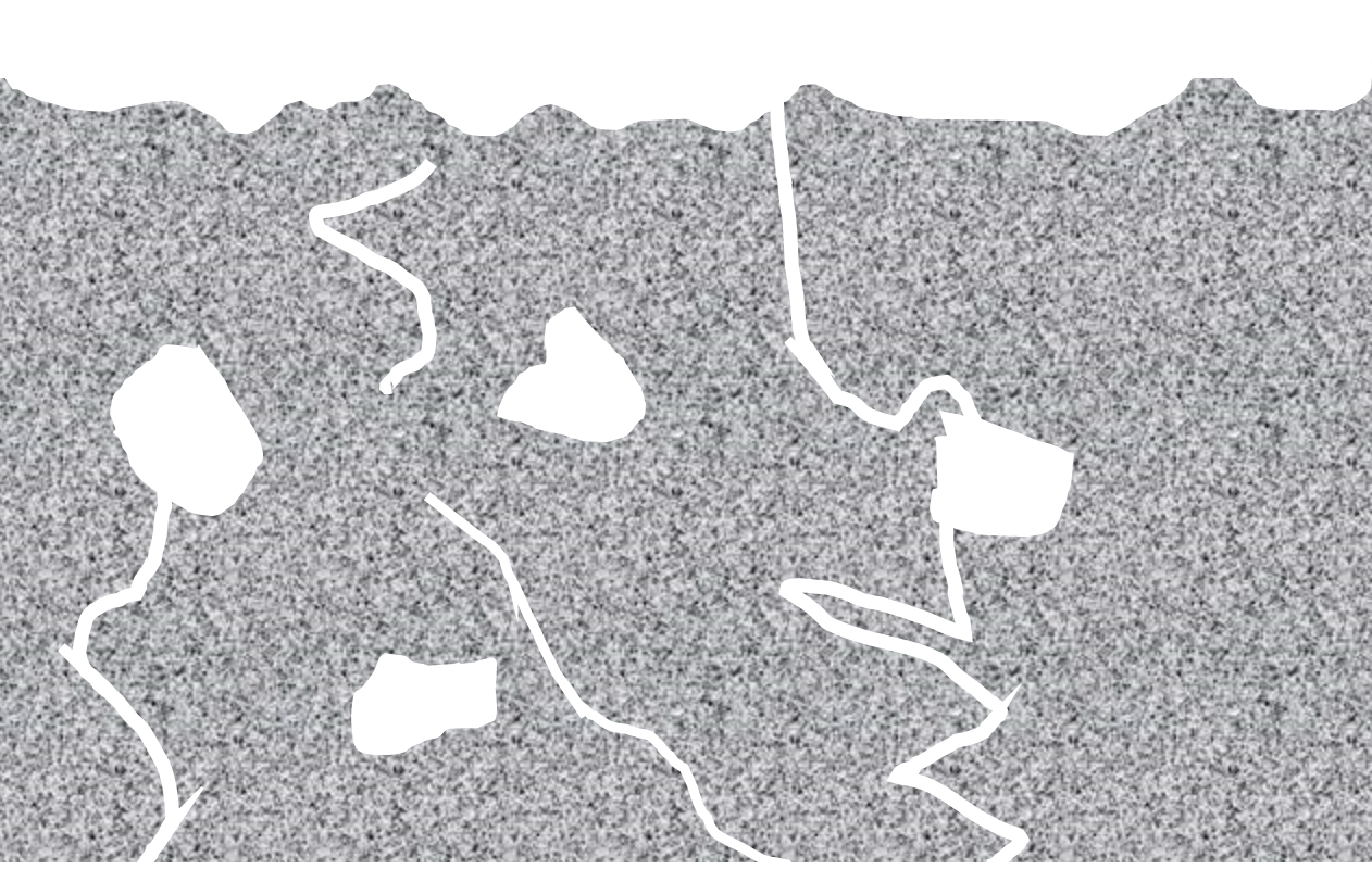
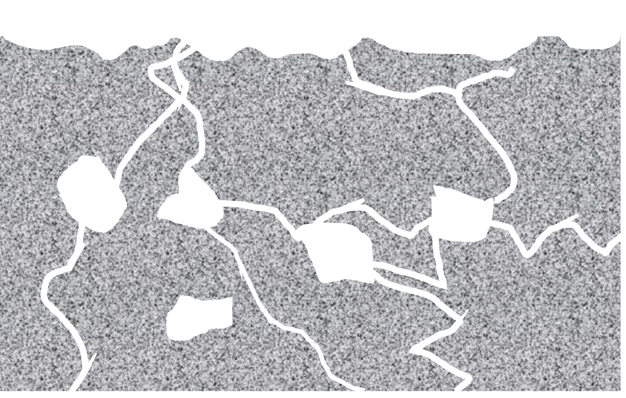
Therefore, a shell may be highly porous, but not permeable if the air does not have a passage to escape the shell. Luckily in shell systems this is not the case but remember a porous shell does not mean a permeable shell. This is highlighted within figure 1 below.
 |
 |
|
Porous shell with low permeability |
Porous shell with higher permeability |
|
Figure 1: Porosity vs. Permeability |
|
With this in mind it is correct to say a shell with high permeability is porous but a shell with high porosity is not necessarily permeable!
Porosity directly competes with the shells ability to maintain strength as outlined by the Ryshkewitch Duckworth equation [1]. Where the increase in voids or porosity within a sample reduce the strength of the sample as per the equation below. 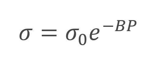
where σ is the strength of the porous body, σ0 is the strength of a non-porous body of the same material and P is the porosity of the sample expressed as a fraction. B is a constant.
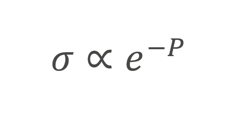
This tells us that although there is a direct proportionality of the strength of as shell to the porosity within it, for the same material:
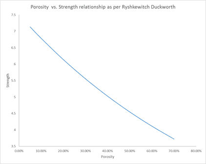
 This can be seen graphically in figure 2.
How is permeability measured?
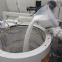
The BSI (BS 1902: Section 10.2:1994) approved method of measuring the permeability of a shell is by using the ping pong ball method [2]. The ping pong ball method is to use a glass rod or impervious mullite rod. It is important to use the appropriate glass rod as failure to do so will result in the rod melting during testing. (This has been experienced on a few occasions within our facility so please consult us regarding the correct type of glass before conducting this test!)
The ping pong ball is coated in slurry and then the ball is burnt out (Figure 3). Air is then passed through the ball at elevated temperatures and the pressure difference is calculated.
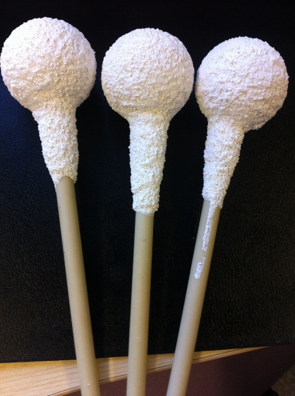
Figure 3 Coated ping pong balls on impervious mullite rods
This pressure drop can then be fed into the permeability equation below to give you a value of permeability:
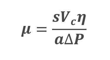
where µ is the permeability, s is the wall thickness of the sample, Vc is the volumetric flow rate, is the dynamic viscosity of air at the elevated temperature, is the inner surface area of the ping pong ball and ΔP is the pressure difference. This measurement technique has some drawbacks:
- Shell samples are prone to cracking and cause inaccurate results. This can be extremely frustrating, and a source of error for the experiment. It is suggested to burn the ping pong ball out extremely slowly to reduce cracking and testing issues.
- This technique can only measure fired samples as it needs to remove the ping pong ball before any testing data can be collected.
- This test method can only measure permeability i.e. connected porosity to the prime layer. This cannot measure the pores not connected to the external surface of the sample. In short, there may be more porosity within your shell owing to the reduction in strength which cannot be measured by this test method.
The benefits of these results however has been the ability to assess the sintering of the ceramic at temperature following a period of time. This shows us how the permeability reduces over time as the ceramic sinters and densifies. This can be seen in figure 4.
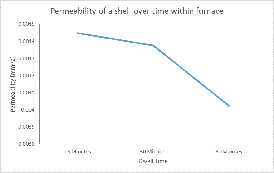
Figure 4 Decrease of permeability over time within furnace
There are ways of increasing permeability within shells:
- Stucco application method – The stucco application method has an impact on the permeability of a shell. As outlined by Jones et al. [3] and myself in a recent ICI paper [4], the stucco application method affects the energy imparted on the slurry and subsequent “compaction” of the stucco layers and subsequent permeability.
- Stucco type – The stucco type has an effect on the permeability of the shell, large particles will have larger gaps between them, leading to increased permeability.
- Reduction in coats – This decreases the distance required for the air to escape and therefore increases the permeability, however it will reduce the strength of the material, so beware!
- Increase Polymer – Increase in polymer concentration, leaving behind larger voids after sintering, increasing permeability.
In summary the permeability of the shell is a useful parameter to understand for shell systems as it can cause headaches and issues for Engineers to solve. Knowing how it is measured and how it can be altered is always useful to remember when the problems arise. The test method has many drawbacks and more scientific methods like CT scanning or SEM microscopy is useful but expensive.
References
- Ryshkewitch, E., Compression Strength of Porous Sintered Alumina and Zirconia. Journal of the American Ceramic Society, 1953. 36(2): p. 65-68.
- BSI, Methods of testing Refractory materials – Part 10: Investment casting shell mould systems — Section 10.2: Determination of permeability and standard air flow capacity at elevated temperatures, in BS 1902-10.2:1994. 1994.
- Jones, S., C. Yuan, and S. Blackburn, Fundamental Study of the Microstructure and Physical Properties of Fluidised Bed and Rainfall Sanding Ceramic Shells, . Journal of Materials Science and Technology, 2007. 23(6): p. 706-714.
- 4. Dooley, G., S Blackburn, S Ramirez, K Williamson, Effect of stucco application method on the mechanical performance and microstructure of investment casting shells. in 60th ICI Technical Conference 2013: Pittsburgh, PN .
Disclaimer
Contact your nearest REMET Sales Office regarding product specifications.
Contact your REMET Territory Manager and visit www.remet.com if you have any questions or require additional information.
Information and/or recommendations based on research and technical data believed to be reliable. Offered free of charge for use by persons with technical skills, at their own discretion and risk, without guarantee of accuracy REMET makes no warranties, express or implied, and assumes no liability as to the use of its products or of any information pertaining thereto. Nothing herein is intended as a recommendation to infringe any patent.
< Back to insights