Stucco Application Methods – The Theory
In the article below, I would like to discuss what the differences are within the two stuccoing methods within investment casting. There have been a few papers presented previously on the subject from Jones [1]. I would to review the work which I conducted during my PhD and presented at an ICI conference in 2013 [2].
There are many factors affecting the stucco application method, therefore I am going begin with the basics of each method. The first article outlines the basics of the process and the theory of application and the energy within the stucco during sanding. We will then look at the effect on the strength of the shell, permeability and microstructure.
It is worth noting that both methods have benefits and constraints for stucco application. Excess sanding using both methods can wear away any sand and cause abrasion.
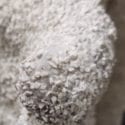
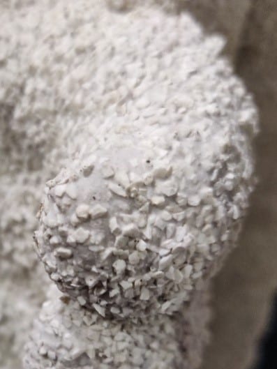 Figure 1 Over sanding of parts cause abrasion and bald patches
Furthermore, some refractories can breakdown during sanding operations leading to an increase in stucco fines or dust within the system. This dust then covers the wet slurry and reduces sand pickup, causing thinner, weaker shells. Stucco fines are a key property which must be considered. Equipment manufacturers and material suppliers must monitor this property using extraction during manufacture and processing.
Rainfall Sanding
Overview
Rainfall sanding consists of sand being “rained” down on the wet slurry. There are two methods this can be achieved. As per figure 2, (a) vertical and (b) rotary are two methods of rainfall sanding. This system is a “line of sight” system whereby the sand falling must be applied to the wet shell.
One feature of these systems is the auto sieving of the sand during application which reduces clumps of sand (snurds, crispies etc.) being applied to the shell.
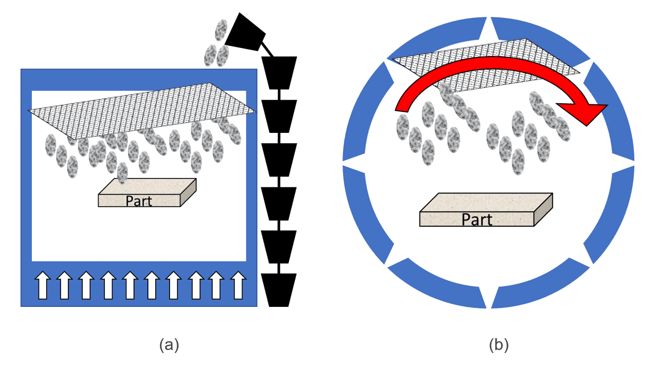
Figure 2 Rainfall sanding variations (a) bucket or auger rainfall sander and (b) rotary rainfall sander
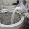
Fluidised Beds
Fluidised beds are used widely in many applications including pharmaceutical and food processing industries [3]. A fluid bed is formed by passing a fluid, usually a gas (air) upward through a bed of particles supported on a distributor [4]. This method can be used effectively if there are blind holes and shadowed areas which require coverage. This process however requires stricter process control, and regular sieving maintenance to ensure effective coating of the shells.
Within fluid beds, there are also two variants which are employed to energise the particles. Within figure (a), air jets can be used to fluidise the sand. Alternatively, as per figure 3 (b) a porous ceramic tile sits underneath the sand which is used to disperse the air from under the sand.
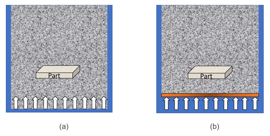 Figure 3 Fluidised bed sanding variations (a) jet fluid bed and (b) porous tile fluid bed
Theory
The velocity of a stucco particle from a rainfall sander before impacting the shell can be calculated using the terminal velocity model of a particle:
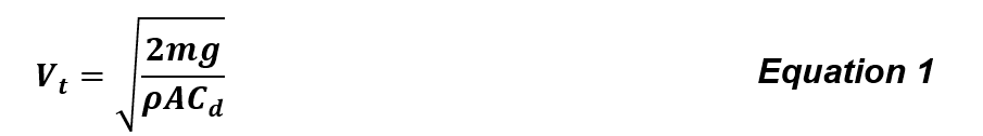
Where m is the mass of the particle, is the acceleration due to gravity, ρ is the density of the fluid, A is the area of the particle and Cd is the coefficient of drag. The Kinetic Energy can be subsequently calculated using Equation 2:
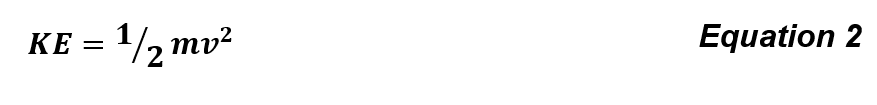 Where m is the mass of the object and v is the velocity.
Fluid beds exhibit the following properties [4]:
- The particles behave like a liquid of the same bulk density
- The pressure within the bed varies with depth
- Particle motion is rapid – leading to good mixing
- A high particle surface area is available
For investment casting applications, the properties of the particles and subsequent fluidisation resembles group B particles as outlined by Geldart groupings in Figure 4 [5]
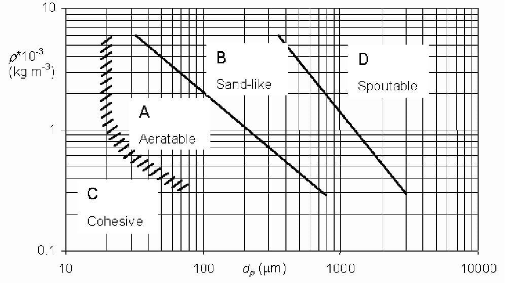
Figure 4 Geldart particle groupings [3]
The properties of a group B particle are [5]:
- Inter-particle forces are negligible
- Bubbles are formed as the gas velocity reaches the minimum fluidisation velocity
- Bed expansion is small
Bubble size increases in increasing gas velocity
For fluid beds, the Ergun equation can be utilised to measure the pressure drop within a fluidised bed. The Ergun equation can be written as [4]:
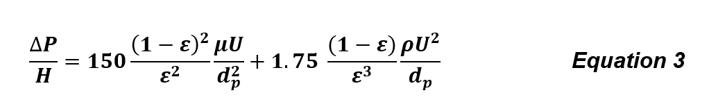
where:
ΔP= Pressure drop across the fluid bed
H = the height across the pressure drop
ε = Particle void fraction
dp = Particle diameter
U = superficial fluid velocity
ρ = fluid density
µ = fluid velocity
Using these equations, and utilising empirical evidence obtained by in process measurement, the energy of a standard back up stucco was calculated. For the calculation an 80 µm aluminosilicate particle (assumed to be spherical), was used.
There is a difference by a factor of approximately 25 times between rainfall sanding and fluidised beds. For rainfall sanding, the calculated energy was 2.8 x 10⁻⁵ J. Solving for U in equation 3, the velocity of a stucco particle within the bed was found to be 0.085 m s-1. while for fluid bed application, the energy per particle was calculated as 1.15 x 10⁻⁶ J. While this is a large difference in energy, there are still benefits for both systems.
Summary
There are positives and negatives related to both stucco application methods. Some in process benefits are present using either method. There is a large difference in the energy imparted by the particles, and therefore this will affect the mechanical and microstructural performance of a shell. In the next article we will review this in further depth. Stay tuned!
References:
[1] Jones, S., C. Yuan, and S. Blackburn, Fundamental Study of the Microstructure and Physical Properties of Fluidised Bed and Rainfall Sanding Ceramic Shells, . Journal of Materials Science and Technology, 2007. 23(6): p. 706-714.
[2] Dooley, G. et al. “Effect of Stucco Application Method on the Mechanical Performance & Microstructure of Investment Casting Shells”, Oct 9, 2013, 60th ICI Technical Conference, Pittsburgh, PN
[3] Technology, A.C. Fluid Bed Systems. Available from: http://www.appliedchemical.com/products/fluid_bed_systems/.
[4] Seville, J., Fluidisation of Cohesive Particles, in Granulation. 2007, Elsevier. p. 1041-1069.
[5] Geldart, D., Types of Gas Fluidization. Powder Technology, 1973. 7(5): p. 285-292.
< Back to insights