Investment Casting Strength – Part 3: Shell materials
If you are still reading this series, then you have come through a journey of discovery of strength and how it affects our materials for investment casting. This last article describes the intricacies of testing ceramics and how a deeper understanding of what and how we are measuring will allow a better insight into the material.
Within part 1 and part 2 we discussed the fundamentals of strength, how it is measured, what happens within the material during testing and what the stress strain graph can tell us about the material. Now let’s move onto materials themselves, particularly the shell which can cause such heartache and issues for the calmest of foundry engineers!
Some questions we should ask ourselves:
Is the strongest shell possible the holy grail? During what process should I have the highest strength in my shell? Is strength the best measure of the properties I require? All of these questions underpin what the requirements for a shell is through the different stages before it is finally removed and we hold our breath to see the results…
Jones et al. summarised the requirements of a shell in 2003 [1]:
- Sufficient green strength to withstand wax removal without failure
- Sufficient fired strength to withstand pressure of cast metal
- Sufficiently weak to prevent hot-tearing in susceptible alloys
- High thermal shock resistance to prevent cracking during metal pouring
- High chemical stability
- Low reactivity with the metals being cast to improve the surface finish
- Sufficient mould permeability and thermal conductivity to maintain an adequate thermal transfer through the mould wall allowing the metal to cool
Arguably you could add two more requirements to this list:
- Sufficiently weak to allow for shell removal post casting
- Sufficient integrity to reduce breakdown during metal casting
This seems like a lot of requirements on one shell system however it is achievable and possible for a shell system to meet and exceed these expectations – or else we wouldn’t have a very capable process!
Starting at the beginning, the shell must be sufficiently strong to withstand any stresses during drying onset by drying and subsequent contraction. This contraction and variability can be better managed by environmental control (airflow, temperature, humidity) which is optimised for the process. This strength is extremely hard to measure and can only really be assessed when the part is in metal.
The next pivotal stage is the de-wax process. During this process the material should be strong enough to withstand the expansion of the wax while melting. We test during the green state to assess the strength of the shell during this stage.
While all these can be measured and analysed or trended, what does a MOR value tell us about the material. This is where it gets tricky!
Right, so the MOR value is measured in MPa or N/m2 when we talk about SI units. So this is saying it takes X amount of Newtons (force) to break 1 m2 of the material. Therefore, theoretically the strength of the material doesn’t change across the different thickness of the same material. This can be seen graphically within figure 1.
Figure 1 Force (black) changes as thickness increases but MOR (orange) stays constant as it is independent of thickness
The strength of the material should be independent of the thickness of the material and only a property of the materials and processing involved. This is worth keeping in mind when you add a few coats onto your shell system and your MOR doesn’t increase as expected. This was shown within a paper from Jones and Jolly from the University of Birmingham in 2001 [2]. What will change is the force required to break it, however due to the increased thickness, the MOR should not move. In practice, life is not so simple as this however and other factors affect the strength for given thicknesses. When the thickness increase we are measuring over a larger area where possible cracks can be present which can affect the MOR for different thicknesses. Briefly touching on theory (again!) this is down to the Griffith’s theory of crack propagation which states the fracture strength (?f) is proportional to the crack length (a) within the sample [2].
 This means the larger a is the lower the stress at failure. This is also complemented by the empirical equation given by Ryshkewitch Duckworth [4]. Where the increase in voids or porosity within a sample reduce the strength of the sample as per the equation below.

where ? is the strength of the porous body, ?0 is the strength of a non-porous body of the same material and P is the porosity of the sample expressed as a fraction. B is a constant.
Crack location also has a large effect on the strength unfortunately. As we are dealing with non-homogenous ceramics, tensile testing is not possible. Therefore, as discussed in part 1, the flexural method does not impart the same stresses across the sample. Take a cross section of a shell (with voids) which are axially loaded during testing as per figure 2.
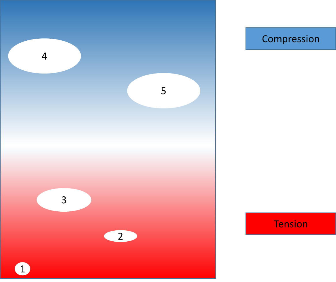 Figure 2 Cross section of a ceramic shell with voids 1-5 during loading
Within this figure, voids 4 & 5 potentially do not cause any failure of the material due to being in compression. Without accurate calculations, it is also difficult to assess which void 1,2 or 3 will result in the failure of the ceramic. Although void 3 is the largest, it will be undergoing the least stress as it is closer the neutral axis during loading (refer to article 1). Conversely, although void 1 is small, it is subjected to the highest stress and may fail first. (Obviously this is an extreme scenario used to convey the physical behaviour of the system!)
I hope at this point also you are asking, what are we actually testing? Well, even with these complexities added into our flexural testing, we are still testing the strength of our shell which will cause us problems during casting.
However, what we need to consider is what part of the shell are we testing? As we test with the prime coat on the supports of a test fixture, the prime coat undergoes the maximum force and fails as a result. Only if the secondary coats are as stronger than the prime coat (which is unlikely!), will the failure occur in the back up layers. Within my own work I have had countless results where changes to the BU layer has not resulted in any change to the overall strength when tested with the prime coat is in tension, therefore changes to the backup which are being measured I believe need be measured with the backup coats on the supports. Or alternatively, a shell made up of only these layers can be best to analyse strength which you are attempting to measure.
Conclusions
The strength of materials is paramount to the success of a robust IC process. The ceramic shell has many requirements for strength and these must be sufficiently managed to give you a robust system. It is important to understand the relationship between how and what you are testing to ensure you can deduce the weaknesses within your shell system.
References
- Jones, S. and C. Yuan, Advances in shell moulding for investment casting. Journal of Materials Processing Technology, 2003. 135(2–3): p. 258-265
- Jones, S., M. Jolly, and K. Lewis. Development of “Rule of Mixtures” Techniques For Predicting Ceramic Shell Properties For Investment Casting. in FOCAST 2nd Mini-Conference. 2001.
- Griffith, A. A., The phenomena of rupture and flow in solids , Philosophical Transactions of the Royal Society of London, 1921, 221: 163–198
- Ryshkewitch, E., Compression Strength of Porous Sintered Alumina and Zirconia. Journal of the American Ceramic Society, 1953. 36(2): p. 65-68.
Disclaimer
Contact your nearest REMET Sales Office regarding product specifications.
Contact your REMET Territory Manager and visit www.remet.com if you have any questions or require additional information.
Information and/or recommendations based on research and technical data believed to be reliable. Offered free of charge for use by persons with technical skills, at their own discretion and risk, without guarantee of accuracy REMET makes no warranties, express or implied, and assumes no liability as to the use of its products or of any information pertaining thereto. Nothing herein is intended as a recommendation to infringe any patent.
< Back to insights